Iranian Classification Society Rules

< Previous | Contents | Next >
Section 1 General Requirements of Stability
101. General
1. All units are to have positive stability in calm water equilibrium position, for the full range of draughts when in all modes of operation afloat, and for temporary positions when raising or lowering.
2. In addition to Par 1, all units are to meet the stability requirements set forth this Chapter for all applicable condition.
102. Intact stability
1. All units are to have sufficient stability (righting ability) to withstand the overturning effect of the force produced by a sustained wind from any horizontal direction, in accordance with the stability criteria given in Sec 2, for all afloat modes of operation.
2. Realistic operating conditions are to be evaluated, and the unit is to be capable of maintaining in operating mode with a sustained wind velocity designated by the Owner, but not less than 36 mÕsec (70 knots).
3. The capability is to be provided to change the mode of operation of the unit to that corresponding to a severe storm condition, with a sustained with velocity of not less than 51.5 mÕsec (100 knots),
in reasonable period of time for the particular unit. In all cases, the limiting wind velocities are to be specified and instructions should be included in the Operating Booklet for changing the mode of operation by redistribution of the variable load and equipment, by changing draughts, or both.
4.
For restricted operations consideration may be given to a reduced sustained wind velocity specified in Par 2 and 3, of not less than 25.8 mÕsec (50 knots).
For the purpose of calculation, it is to be assumed that the unit is floating free of mooring
5. restraints. However, the possible detrimental effects of mooring restraints are to be considered.
103. Damage stability
1. All units are to have sufficient stability to withstand the flooding from the sea of any single compartment or any combination of compartments consistent with the damage assumption set out in 104., for operating and transit modes of operation.
2. The unit is to possess sufficient reserve stability in the damaged condition to withstand the addi- tional heeling moment of a 25.8 mÕsec (50 knots) sustained wind superimposed from any direction.
3. The final waterline is to be below the lower edge of any opening which is not to comply with the requirements in Ch 6, 202. and 203. so that the unit has the sufficient stability to withstand the
heeling moment.
4. For all types of units, the ability to compensate for damage lasting other compartments, etc., is not to be considered as herein.
incurred, by pumping out or by bal- alleviating the requirements specified
5. For the purpose of calculation, it is to be assumed that unit is floating free of mooring restraints.
However, the possible detrimental effects of mooring restraints
are to be considered.
![]()
104. Assumption of the damage extent
1. Damage extent of self-elevating units
In assessing the damage stability as required by 103., the following extent of damage is to be as- sumed to occur between effective watertight bulkheads.
(1) Horizontal penetration : 1.5 m
(2) Vertical extent : bottom shell upwards without limit.
(3) The distance between effective watertight bulkheads or their nearest stepped portions which are positioned within the assumed extent of horizontal penetration should be not less than 3 m;
where there is a lesser distance, one or more of the adjacent bulkheads should be disregarded.
Where a bottom mat is fitted, assumed damage penetration simultaneous to both the mat and the upper hull need only be considered when the lightest draught allows any part of the mat to fall within 1.5 m vertically of the waterline, and the difference in horizontal dimension of the upper hull and mat is less than 1.5 m in any area under consideration.
(4) If damage of a lesser extent than specified in (1) to (3) results in a more severe final equili-
brium condition, such a lesser extent is to be assumed.
(5) All piping, ventilating systems, trunks, etc., within this extent are to be assumed damaged.
(6) Positive means of closure are to be provided to preclude progressive flooding of other intact spaces.
(7) The compartments adjacent to the bottom shell are also to be considered flooded individually.
2. Damage extent of column-stabilized units
In assessing the damage stability as required by 103., the following assumed damage conditions apply.
(1) Only those columns, underwater hulls and braces on the periphery of the unit are to be as- sumed to be damaged and the damage is to be assumed in the exposed portions of the col- umns, underwater hulls and braces.
(2) Columns and braces are to be assumed to be flooded by damage having a vertical extent of 3.0 m occurring at any level between 5.0 m above and 3.0 m below the drafts specified in the Operating manual. Where a watertight flat is located within this region, the damage is to be as- sumed to have occurred in both compartments above and below the watertight flat in question. Lesser distances above or below the draughts may be applied taking into account the actual op- erating conditions. However, the extent of required damage region should be at least 1.5 m above and below the draft in question.
(3) Horizontal penetration of damage is to be assumed to be 1.5 m .
(4) No vertical bulkhead is to be assumed to be damaged, except where bulkheads are spaced clos-
er than a distance of one eighth of the column perimeter at the draught under consideration,
measured at the periphery, in which case one or more of the bulkheads are to be disregarded.
(5) Footings or lower hulls are to be treated as damaged when operating at a light or transit con- dition in the same manner as indicated in (1) to (4).
(6) If damage of a lesser extent than specified in (1) to (5) results in a more severe damage equili- brium condition, such a lesser extent is to be assumed.
(7) All piping, ventilation systems, trunks, etc., within this extent of damage are to be assumed
damaged.
3. Damage extent of surface type units
In assessing the damage stability as required by 103., the following extent of damage is to be as- sumed to occur between effective watertight bulkheads.
(1) Horizontal penetration : 1.5 m
(2) Vertical extent : bottom shell upwards without limit
(3) The distance between effective watertight bulkheads or their nearest stepped portions which are
positioned within the assumed extent of horizontal penetration should be not less than 3 m; where there is a lesser distance, one or more of the adjacent bulkheads should be disregarded. If damage of a lesser extent than specified in (1) and (2) results in a more severe final equili- brium condition, such a lesser extent is to be assumed.
(4) All piping, ventilation systems, trunks, etc., within this extent are to be assumed damaged.
(5) The compartments bounded by the bottom shell are to be considered flooded individually.
![]()
105. Damage stability of column-stabilized units
The column-stabilized unit is to comply with the following in addition to 103.
1. The column-stabilized units are to have the sufficient stability to meet following under the wind force specified in 103. 2.
(1) The angle of inclination after the damage set out in 104. 2 (2) is not to exceed 17°.
(2) The final waterline is to be located below the lower edge of any opening that does not meet the requirements in Ch 6, 202. and 203. However, no openings are provided in column. The openings within 4 m above the final waterline are to be made weathertight.
(3) The righting moment curve, after the damage, is to have from the first intercept with the wind
heeling moment to the lesser of the extent of weathertight integrity or the second intercept, a range of at least 7°. Within this range, the righting moment curve is to reach a value of at
least twice the wind heeling moment curves, both being measured at the same angle. (See Fig
7.1).
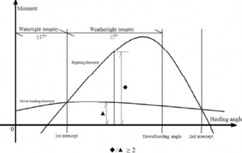
Fig 7.1 Residual damage stability requirements for column- stabilized units
2. The column-stabilized unit is to have sufficient buoyancy and stability to meet the following, in any operating or transit condition with the assumption of no wind to withstand the flooding of any watertight compartment wholly or partially below the waterline in question, which is a pump-room, a room containing machinery with a salt water cooling system or a compartment adjacent to the sea.
(1) The angle of inclination after flooding is not to be greater than 25°.
(2) The final waterline is to be located below the lower edge of any opening that does not meet the requirements in Ch 6, 202. and 203. However, no openings are provided in column.
(3) Sufficient margin of stability is provided which requires a range of positive stability of at least
7° beyond the first intercept of the righting moment curve and the horizontal coordinate axis of the static stability curve to the second intercept of them or the downflooding angle, whichever
106. Damage stability of self-elevating units and surface type units
1. The self-elevating unit and surface type unit are to comply with
2. The flooding of any single compartment of the self-elevating unit rion (see Fig 7.2):
the requirements in 103.
while meeting the following crite-
ĈᾫĊ ≥ Kᾫ Ñ NÌǾJß ᾯ Ń
where,
ĈᾫĊ ≥ ÌLᾫ
![]()
ĈᾫĊ : range of stability, in degrees Ņ ßᾩ Ň ßᾯ
where,
ß ᾩ : maximum angle of positive stability, in degrees
ß ᾯ : static angle of inclination after damage, in degrees
The range of stability is determined without reference to the angle of downflooding.
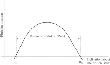
Fig 7.2 Residual Stability for Self-elevating Units
107. Inclining test
1. An inclining test will be required for the first unit of a design when as near to completion sible, to determine accurately the light ship weight and position of centre of gravity.
2. An inclining test procedure is to be submitted to the Society for review prior to the test. clining test is to be carried out in the presence of the Surveyor.
as pos- An in-
3. For successive units of design, which are basically identical with regard to hull form, with the ex- ception of minor changes in arrangement, machinery, equipment, etc., and with concurrence by the Society that such changes are minor, detailed weight calculations showing only the differences of weight and centres of gravity will be satisfactory, provided the accuracy of the calculations is con- firmed by a deadweight survey.
4. The results of the inclining test, or deadweight survey and inclining experiment adjusted for weight differences, are to be reviewed by the Society prior to inclusion in the Operating Booklet.
![]()